|
The S-Series of the Metlund® Hot Water D’MAND® System is easy to install. The modular design simplifies installation. There are three ways to view the installation procedures. Click the links below to view written instructions, photos and/or video:
S-Series Installation Instructions
Photographic Step-By-Step Installation
Installation Video
Installations shall be in accordance with the manufacturer’s instructions per the requirements of the Uniform Plumbing Code (UPC)
Be Careful - Do not plug the power cord into an electrical receptacle until system is instal LED and in place. Operation of the system without being plumbed into the water lines may burn out the pump prematurely and void the warranty.
Pre-Installation Checklist
1. Check the package contents. Your Metlund System includes:
- A pre-assemb LED Metlund Controller/Circulator Pump/Zone Valve Assembly
- S-50 and S-70T models will not show zone valve. Zone Valve is inside the pump housing.
- Compression fit copper T’s. Homes with galvanized pipes will need galvanized T’s.
- A plastic bag containing: one (1) push-button
- (If wireless remote option was purchased) one transmitter, one receiver, one 12V Battery, three gray wire nuts & three screws.
- Check the components for visible damage and contact your supplier immediately if any damage is found.
2. Make sure you have the tools to do the job
No special tools are required to install the Metlund System other than those tools usually needed in any plumbing job. They include:
- Pipe wrench or crescent wrench
- Pliers
- Small Phillips head and medium flat head screwdriver
- Wire strippers
- Drill and 5/8" drill bit
- Soldering equipment (if applicable)
3. Determine where you will install The System
Typically, this should be at the fixture farthest away from the water heater. If your hot water supply line runs in two separate directions from the water heater, you may need more than one Metlund System to satisfy all of your hot water requirements.
Installing The Metlund D’MAND for all S-Series Systems
This is for installation of the Pre-Fab Accessory T’s only. These do not replace the existing instructions included with your system. Be sure you have read the instructions carefully before proceeding with your installation.
You have purchased a Metlund Hot Water D'MAND System that is equipped with the pre-fab accessory package. The ½" male thread adapters have already been pre-sweat to your Metlund System.
Enclosed with your system, are two T’s designed to simplify your installation to ½" copper hot and cold supplies. (Additional fittings may be required if your supply lines are galvanized or plastic pipe. )
To Install Your “T” Fittings
- Turn off the house water supply.
- Open the hot and cold faucets at the fixture chosen for installation. This will relieve the water pressure from the hot and cold water pipes.
- Remove the shut-off valves that supply hot and cold water to the sink from the ½" copper pipe. For ease of installation, leave the compression ring and nut from the angle stop on the hot and cold water supplies.
Remove the compression ring and nut from the enclosed compression fitting on the PF-T’s, and slide onto the other end. Attach the existing nut and ring to the end of the threaded T and firmly tighten.
- Install the remaining compression ring and nut to the shut-off valve,slide onto the ½" side of the PF-T and firmly tighten.
- Now you are ready to attach flex lines from the ½" male thread of the PF-T’s to your Metlund D’MAND System. (Teflon tape is recommended for the ½" threaded fittings.)
- Refer to Page 3 - “Installing the Demand Button(s)” and “Wireless Remote Option”.
Installing The Metlund D’MAND for all S-Series Systems
The system adapts to your existing plumbing! Follow these simple steps: METLUND "NO SWEAT"
|

|

|

|

|
| 1. Turn off water supply and remove angle stops. |
2. Install & tighten T's (included), attach angle stops. |
3. Install copper flex lines or any line with ½" inside diameter. |
4. Connect Metlund System, install push button and plug in. |
Installation must be as shown above
1. Installation Procedures
- A. Turn off the house water supply
- B. Open the hot and cold faucets at the fixture chosen for installation. This will relieve the water pressure from the hot and cold water pipes
- C. Remove the shut-off valves that supply the hot and cold water to the sink
- D. Install T-fittings to the pipe stubs from the hot and cold water supply
NOTE: Using piping with less than 1/2" inside diameter will restrict the flow of the water, causing it to take longer for hot water to arrive. Before sweating 1/2” pipe to zone valve, be sure zone valve is in manual open position
- E. Install the Metlund System between the hot and cold lines, but be sure that the arrows on the pump and the valve point from the hot side to cold as shown in Figure 1
- F. Re-install the shut-off valves to the water supply and sink
2. After installation adjustments
Check the system carefully to make sure the installation is free of water leaks.
All Electronic Sensitivity Adjustments are pre-set at the factory. If adjustments are necessary please call for technical help prior to making any adjustments. However, please make sure the off sensor (green tip wire), is firmly attached and is touching the pipe. The sensor is designed to signal the controller to shut off automatically when hot water has reached your fixture, and not to reactivate if hot water is at the fixture. Review the troubleshooting page for additional information.
3. Try the Metlund System and check water temperature
Once installed, turn water supply on and plug in the system. (Pump will automatically turn itself on when it is initially plugged in without pushing the demand button). The Metlund System will continue to operate until the sensor signals that hot water has arrived, then it will automatically shut off. To test the system again, wait until pipes cool down. You may then test the system by pushing the demand button, or to pre-test your system after plugging the unit into 110v outlet, place a hot rag over ThermoSensor located to the right of the pump housing.
The unit will shut off immediately. Remove rag from sensor and test remote control buttons.
To operate the Metlund System from another location in the home, place remote button in desired location. Push remote button, wait a few seconds for system to cycle. You may now turn on hot water. Time for hot water to arrive may vary depending on pipes and distances. The Metlund System is designed to electronically shut off at a slight temperature rise preventing warm water from entering into the cold water line. The electronic ThermoSensor™ adjusts automatically to line temperature. Object: To move hot water to your fixtures quickly, shutting off quickly
NOTE: The Metlund Electronic Controller is designed with an automatic safety feature that will shut off the pump in approximately three minutes. This safety device was installed in case the ThermoSensor™ becomes damaged.
4. Installing the Demand Button(s)
A. Drill a 5/8" hole into the desired location.
B. Insert the 5 foot gray wire from the controller through the back side of the hole and connect it to the push button switch. Then, firmly insert the push button back into the hole. Additional push button switches can be spliced into the same wires. It is important to use a button comparable in quality to the button provided.
88Wireless Remote Option - R-0954
(Standard with all S-50-PF-R, S-70T-PF-R, or S-02-PF-R)
Wiring The Receiver
The remote receiver is the white rectangular box with the three protruding wires: black, white & green. This does not need batteries. Wire the receiver directly to the corresponding wires on the controller by twisting each same colored wire together with gray wirenuts provided.
Receiver should be mounted toward front of cabinet. (Range of transmitter is about 100’). If transmitter will activate system from short distance, but not from further away, receiver may need to be relocated for better reception. Strapping receiver to front of drain trap facing outward will optimize reception.
Installing Batteries to the Transmitter
Open transmitter with a small flat head screwdriver by inserting screwdriver into slot to release catch. Load Battery with negative side of Battery toward spring. Carefully replace cover. Numbered jumper pins are inside the transmitter and receiver. The signal frequency can be changed by removing the same numbered pins from both the receiver and transmitter. This should only be necessary when two D’MAND® Systems are in same home or your neighbor has the system.
 |
Installing The Metlund D’MAND System for S-02 |
1. Check the package contents. Your Metlund System includes:
S-02 MODEL 0011 PUMP (ONLY)
- A pre-assembled S-02 pump/zone valve assembly
- Set of flanges + gaskets
- A plastic bag with 2 zip-ties, 1 push-button
- A 3/4” threaded reducer to sweat 1/2” pipe
S-02-PF-R MODEL 0011 PUMP (ONLY)
- A pre-assembled S-02 pump/zone valve assembly
- Set of flanges + gaskets • Set of T’s
- Set of Flex-line • One double threaded elbow
- A plastic bag with 2 zip-ties • An R0954 remote control package
2. Installing the System
Flange Setup
Lay pump out with electrical box on top & flange fitting to rear. Open box with flange parts and layout. For each side of the pump’s flange fittings, you will need: 2 nuts, 2 bolts, 1 flange plate, 1 gasket & 1-3/4 female ball valve housing (FBVH). Note that on one side of the flange plate is an indentation for the FBVH to set into. Set into position and place gasket over this assembly. Next, set gasket side of assembly against flange fitting on pump and secure with nuts and bolts provided. Leave fairly loose until other parts are added. Repeat to other side of pump. (Note: On the FBVH is a flat head screw adjustment that closes off the water supply by adjusting the screw perpendicular which closes the ball valve should pump replacement be necessary. This adjustment set in the horizontal position would be full open.)
Attaching Zone Valve & 3/4 Male Elbow
The zone valve has two male fittings attached. The straight piece is on the incoming side of the valve and the elbow on the outgoing side. Place Teflon tape on the incoming thread and screw on outgoing side of pump onto FBVH. (Left side as pictured or see arrow on bottom of pump) Next, place Teflon tape onto the male fitting on the shorter side of elbow. Screw this into place on the FBVH attached to the incoming side of pump. Both of the male fittings should be pointing upward, then nuts & bolts of the flange assembly should be tightened in place.

*S-50 models do not have zone valve shown above.
 |
Photographic Step-By-Step Installation |
 |
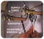
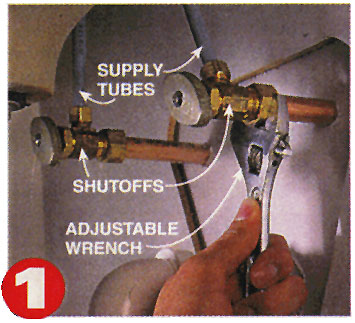
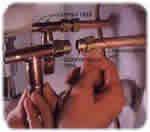
1. Remove the shutoffs under your sink after turning off the main water supply. Be sure to open the water valve outside to relieve the pressure in plumbing lines. The shutoffs shown here are attached with compression fittings that you can remove with an adjustable wrench. If your shutoffs are soldered on, remove them with a mini tubing cutter or a hacksaw, cutting as close to the shutoff as possible. |
 |
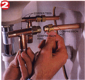
2. Before installing copper the T's, remove the compression nut from the threaded end and slide onto the opposite tapered end of the T. Install the copper that comes with the pump unit onto the hot and cold water lines. You can use the compression ring and the compression nut from the shutoffs, since a previously used compression ring usually can't be removed without cutting the pipe. Tighten the compression nut with an adjustable wrench. |
 |
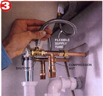
3. Mount the hot and cold shutoffs on the unthreaded end of the copper tees, using the compression ring and compression nut that comes with the tees. |
 |
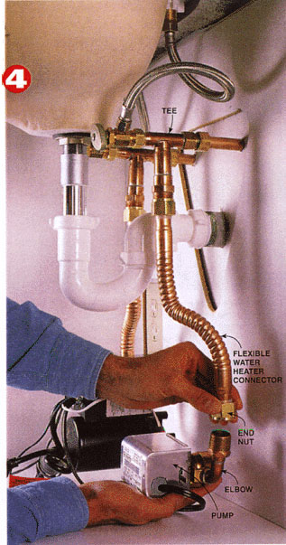
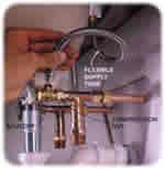
4. Attach the two ¾" flexible water heater connectors to the tee bottoms, then to the threaded elbows of the pump unit. Bend the flexible connectors gently into shape to line up the end nuts with the threads on the pump elbow. Secure all four of the end nuts with an adjustable wrench. The Pump unit can either hang suspended on the connectors, or rest on the floor of the cabinet, since there is no noise or vibration |
 |
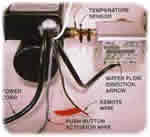
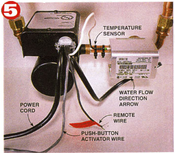
5. Note the arrow indicating the water-flow direction. Water must flow from the hot to the cold line. Note also the temperature sensor, which shuts off the pump when hot water reaches the unit. The push-button activator wire runs to the push button shown in Step 6. The remote wire attaches to the remote master unit (Step 7). The power cord plugs into a standard 120-volt electrical outlet under the sink. |
 |
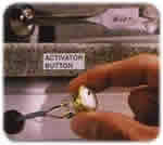
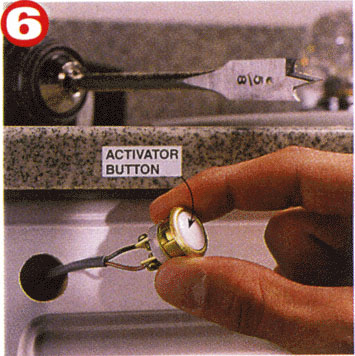
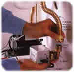
6. Drill a hole in a convenient location in the cabinet near the sink and mount the push-button activator that's supplied with the pump unit. Connect it to the pump-activator wire shown in Step 5. |
 |
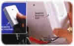
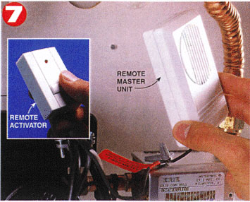
7. Connect the remote receiver unit to the remote wire on the pump. Mount the remote receiver unit anywhere under the sink. The remote transmitter button can be used at any other sink on the hot water line, up to 75'' away, even through walls and doors. |
 |
|
Warning:
If your home has a Pressure Regulator Valve that acts as a back flow prevention valve, you must have an expansion tank in the system before installing a D’MAND System.
|