|
Before You Start, Be Prepared!
Because the Seisco Fluid Heating System is powered by electricity, and has an electronic control system, it is necessary to have a battery powered volt/ohm multi-meter and a clamp-on amp meter for troubleshooting. For instance, if a diagnostic code appears for a bad element, it will be necessary to use an ohm meter to determine which element is bad. See Required Test Equipment & Techniques for Measurements below for additional details on the tools necessary for testing and servicing the heater.
Required Test Equipment
It is necessary to have the proper tools and testing equipment before attempting to trouble shoot or service a Seisco heater. As alluded to in the paragraph above, Performing Service Calls, the following test equipment is required:
- A multi-meter, preferably with a digital read-out; capable of measuring AC (Alternating Current) voltage up to 600 volts. Also, the multi-meter should be capable of measuring resistance (or continuity) in ohms, up to 1 kilo-ohms (1000 ohms).
- A clamp-on ampere meter; capable of measuring up to 120 amps. A deflection needle type or digital read-out amp meter is suitable. A deflection needle type may be easier to read due to the modulating characteristics of the Seisco control.
- A digital thermometer; capable of measuring water temperatures up to 180 degrees F.
- A one gallon bucket and stop watch (or wrist watch) for measuring flow rates.
- A set of basic hand tools, including a slotted screwdriver, a Phillips head screwdriver, a pair of needle nose pliers, and a set of channel lock wrenches or channel lock pliers.
- For removal and replacement of Seisco parts, it may be necessary to carry an element wrench, large and small Phillips head screw drivers, a set of box wrenches (or crescent wrenches), electrical tape, rags or towels and heat sink compound.
- A torque wrench and screw driver, that measures inch/pounds, is recommended due to required torque specifications on all chamber body and control board components (i.e. for tightening temperature sensors, limit switches, level detect.
Remember, while its important to know and understand the symptoms that have been described by the customer and the ability to verify diagnostic codes that may be present, the not so obvious must not be overlooked. Often plumbing connections as reversed, or there may be leaks at the inlet or outlet connections, disconnected wires, turned-off or mislabeled circuit breakers, too high of a flow rate, etc. Keep it simple and go through the basic Trouble Shooting Check List.
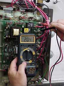 Voltage measurements are taken, with the power turned on to the heater, at the control board lugs, to verify that all wiring is correct and that there is power to all the incoming circuits. The multi-meter should be dialed to AC volts, on the appropriate scale to enable a measurement reading up to 260 volts AC. The voltage across the incoming power lugs on the board must always be measured by placing each of the two multi-meter probes on the control board lugs labeled L1 & L2 for each circuit. (Never measure from one lug to ground in an attempt to verify proper voltage at the circuit). The voltage across the lugs should be between 200 and 250 volts AC. If voltage at any pair of lugs (L1 & L2) is zero, either the power wire legs are out-of-phase or the circuit breaker is turned off or even mislabeled (serving some other device in the home or building). Voltage measurements are taken, with the power turned on to the heater, at the control board lugs, to verify that all wiring is correct and that there is power to all the incoming circuits. The multi-meter should be dialed to AC volts, on the appropriate scale to enable a measurement reading up to 260 volts AC. The voltage across the incoming power lugs on the board must always be measured by placing each of the two multi-meter probes on the control board lugs labeled L1 & L2 for each circuit. (Never measure from one lug to ground in an attempt to verify proper voltage at the circuit). The voltage across the lugs should be between 200 and 250 volts AC. If voltage at any pair of lugs (L1 & L2) is zero, either the power wire legs are out-of-phase or the circuit breaker is turned off or even mislabeled (serving some other device in the home or building).
There could be other reasons for no voltage at the lugs. Check the Trouble Shooting and Diagnostic Code Tables for more details.
Back to Top
|
|


